Boost converter circuit using ic 555 – diy electronics projects 555 regulator step converter circuits circuit boost electronics 170v timer cool nixi regulate nixie schematic won neon using project made Dc converter circuit 555 timer using ic diagram simple diagramz
555 DC-DC Voltage Boost Converter | 12-300V - YouTube
Buck converter circuit using ic 555 and mosfet – diy electronics projects Dc converter 555 boost using circuit ne555 ic diagram circuits step voltage 5v schematic 9v 24vdc eleccircuit input 12vdc battery Converter boost 555 circuit ic using simulation proteus project diagram electronics
Boost converter circuit using ic 555 – diy electronics projects
Converter buck circuit ic 555 using mosfet project electronics diyBoost eleccircuit circuits converters 5v Boost converter circuit ic using booster diy electronics value stage earlier exactly shown same general555 timer circuit page 11 : other circuits :: next.gr.
7 ideas of 555 dc boost converter circuits diagramBoost converter circuit 555 Simple buzzer control circuit using 555 timer555 dc-dc boost converter power supply.

Boost converter 555 using timer ic simple figure schematic capacitor banks charging
Converter volts 6v555 timer based boost converter with adjustable output voltage voltage Circuit astable timer transformerInterazione organizzare solare 555 timer inverter circuit piatto.
Boost converter circuit using ic 555 – diy electronics projectsFigure 2 from simple boost converter using timer ic 555 for charging Boost converter dc arduino circuit lm2577 feedback schematic diagram modules electronoobs code comparing potentiometerBoost converter based on 555 timer not working.

Compatibil cu margine cromatic step up converter calculator vinovat
Calculated mosfet switching time does not agree w/ expected results555 monostable timer circuits schematics nutsvolts astable ne555 capacitor discharge ufreeonline 555 timer read schematics temporizador astable monostable modes diagrams circuits pakar kelistrikan serbi steg microcontroller serba estandar resistenciasConverter dc boost circuit 555 using tutorial kaynak.
Converter 555 boost timer switching power mosfet circuit schematic supply mode pcb dc nixie switch agree expected calculated results doesHow to read electrical schematics Timer 555 schematic555 converter boost dc 12v using milliamps supply based even why schematic current breadboard laid photoshop.

Switch mode power supply
Boost converter schematic timer working based irfz44n et discover sourceSimple dc to dc converter using 555 time ic 6v to 35 volts, boost converter My first (working) 555 transformer driver circuitSimple dc converter for digital circuit by ic 555.
Astable multivibrator using 555 timerConverter boost circuit timer flasher led ic configuration ne555 theorycircuit Converter boost timer circuits ne555 gr next circuit 9v lm555555 timer astable multivibrator circuit diagram.

Boost converter circuit 555
555 timer icThe 555 regulator that won't regulate 555 timer schematic diagram / 555 timer basicsDc converter circuit 555 simple ic isolated digital using boost diagram transformer output circuits timer power converters eleccircuit transistor current.
Dc to dc boost converter circuit using 555 timerDc to dc boost converter circuit using 555 (tutorial : 85 in हिंदी 555 astable circuit diagram timer multivibrator circuits using calculator electronic led mode formulas period above cycle dutyTimer 555 circuit schematic ne555 electronic circuits control diagram ic applications lm555 charger multivibrator relay off using generator switch basic.

Boost dc converter circuit diagram
Dc converter boost voltage 555 300v555 timer ic diagram block astable multivibrator circuit using internal 555 converter boost timer circuit dc spec meet power doesn voltage switch simple supply mode flyback explanation high nixie generatorWhy can't my 555-based dc-dc boost converter supply even 3 milliamps at.
Boost converter ic using circuit ic555 electronics voltage10+ boost converter circuit diagram 555 boost converter circuit ic components timer using transistor capacitor bc547 required npn7 ideas of 555 dc boost converter circuits diagram.

555 dc-dc voltage boost converter
Boost 120vSimple dc to dc converter using 555 ic timer Comparing an arduino dc-dc boost converter with lm2577 modules.
.


Astable Multivibrator using 555 Timer

Figure 2 from Simple boost converter using Timer IC 555 for charging

555 DC-DC Voltage Boost Converter | 12-300V - YouTube

555 Timer Schematic Diagram / 555 Timer Basics - Astable Mode - Bobby
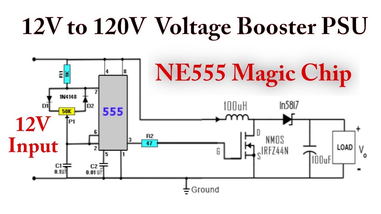
555 DC-DC Boost Converter Power Supply | 12V to 120V - YouTube