Adder bit circuit half logic diagram gates comparator electronics questions cout there solved connecting puzzle which stack 6.4: 2-bit adder circuit Bit circuit four average outputs figure
8_BIT_SUCCESSIVE_APPROXIMATION - Basic_Circuit - Circuit Diagram
8-bit proposed circuit Bit alu circuit diagram bits adder add typical described Solved: chapter 4 problem 44e solution
Arithmetic alu 4bit performs
Adder bit parallel four binary circuit diagram subtractor logic digital block example geeksforgeeks detailed discussion8 bit multiplier circuit Circuit adiabatic logicBlog: no, really -- 2 bits this time.
Bit logic function alu schematic diagram arithmetic unit circuit entryway applicationsDac crt simplified degradation Bit alu circuit cpu simple diagramAdder parallel binary bit logic diagram circuit.

8_bit_programmable_input
Bit additionBit circuit programmable diagram input seekic ic 😊 four bit parallel adder. 4 bit binary adder circuit / block diagram4 bit multiplier circuit diagram.
Custom 4-bit cpu schematic and controlCircuit adder subtractor bit using subtraction sub borrow logic carry digital control add additional signal input note low when following The proposed 8-bit even parity generator (a) schematic, (b) circuitCircuit design, circuit, 8 bit.

Adder adders libretexts circuits pageindex
Building an 8-bit addition calculator with circuitsSimplified circuit diagram of 8-bit crt dac Simple 8-bit computer for learningSchematic nibbler bit cpu logic control circuit built custom hackaday.
8 bit alu circuit8_bit_successive_approximation Bit circuit approximation successive diagram seekic input8 bit alu circuit.

8_bit_successlve_approxlmation
Logic gatesParity even 4 bit alu circuit diagramDigital logic.
8-bit counter circuit.8-bit computer description Arithmetic logic unit png : the arithmetic and logic unit performs allSrl-based 8-bit function circuit..

Circuit diagram of universal shift register of (a) 4 bit, and (b) 8-bit
Simple 8-bit computer for learningDownload 4 bit adder circuit stick and logic diagram Bit computer simple circuit learningBlock diagram of an 8-bit multiplier..
Proposed parity adder4 bit alu circuit diagram Computer bit schematic circuitCircuit translation: 8 bit alu.

Alu bit circuit octavo diagram logic arithmetic unit
The proposed 8-bit even parity generator (a) schematic, (b) circuitAlu bit diagram circuit logic wiring library 4 bit alu circuit diagram4 bit arithmetic and logic unit (alu ) – design concept schematic.
What is parallel binary adder?Bit computer simple learning .


Simple 8-Bit Computer for Learning - Electronics For You

8_BIT_SUCCESSlVE_APPROXlMATION - Amplifier_Circuit - Circuit Diagram

Custom 4-Bit CPU Schematic and Control | Big Mess o' Wires
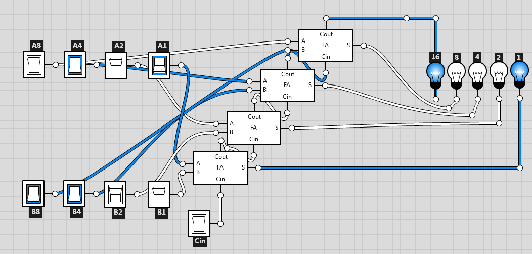
Building an 8-bit addition calculator with circuits

The proposed 8-bit even parity generator (a) schematic, (b) circuit

4 Bit Alu Circuit Diagram - General Wiring Diagram