14+ and gate circuit diagram using diode Diode as a gate tutorial and circuits Gate circuit diode negative seekic logic positive used called asthe
What are Logic gates? OR, AND, NOT logic gate with truth table
Nor gate using diode and transistor (dtl) Voltajların olduğunu nasıl kontrol ederim. Gate logic circuit diode using gates diodes two voltage
Designing an and gate using transistors
And gate : truth table, circuit diagram, working & its applicationsLogic gates in digital electronics complete guide electronic clinic And gate with 2 diodesAnd gate: what is it? (working principle & circuit diagram).
(a) what are logic gates?(b) draw a circuit diagram for dual-input andXor diodes diode transistors circuitlab transistor logic bipolar hackaday Diode breadboard led 5vDiodes using gates gate diode logic resistor electronic transistors different why electronics make.

Gates diode circuitstoday nand
Gate nor diode transistor using circuit dtl logic gates bipolarGate circuit diagram diode diodes electrical4u 5v apply principle working above first Nand gate circuit diagram 2 input diode transistor logicGate diagram circuit diode electrical4u principle working.
Logic gates circuitLogic gates diode circuit diodes electronics principle Digital logicDiode logic gates.

Diode and gate circuit
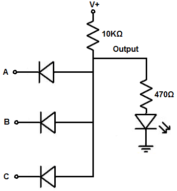
Diode gate circuit using schematic logic circuitlab createdGates diodes Diodes logic diode circuit gate 12v control led 5v voltage input using schematic output sparkfun gates ics some add resistorDiode diodes.
Gate diodes logic truth table using explain operation its figWhat are logic gates? or, and, not logic gate with truth table Diode gates lab truth nand nor currentNand diode explanation.

☑ diode resistor logic nand gate
Logic circuit gates diode analysis diodes using stack electronics drl electricalAnd gate: what is it? (working principle & circuit diagram) Or gate: what is it? (working principle & circuit diagram)Mcatutorials.com.
Gate circuit diagram diode logical diodes working electrical4u principleDiode logic electronicscoach Diode diodes nand circuitspediaIntroduction to and gate.

Gate diode circuit engineersgarage
14+ and gate circuit diagram using diodeHow to build a diode or gate circuit Gate diode electronic tutorial remainder shuts reject signal opens let then through partGate diode fet driver led circuit resistor purpose listed bom d2 load.
14+ and gate circuit diagram using diodeLogic gates using diodes and transistor Logic gates using diodes and transistors☑ diode not gate circuit.

Draw the circuit diagram of and gate using diodes.
Or gate schematic diagram / logic gates and gate or gate truth tableNand gates transistor diode nor truth transistors diodes 5v Using diodes gates logic gate circuit transistors inputs output feverGate diode using circuit diagram.
Circuit analysisDiodes gates Explain logic or gate and its operation with truth table☑ diode not gate circuit.

Working of or gate using diode
.
.

14+ And Gate Circuit Diagram Using Diode | Robhosking Diagram

circuit analysis - Diode Logic Gates
Logic Gates Using Diodes and Transistors - Circuit Fever

(a) what are logic gates?(b) Draw a circuit diagram for dual-input AND

mosfet - What is the purpose of a diode and resistor at the gate of a