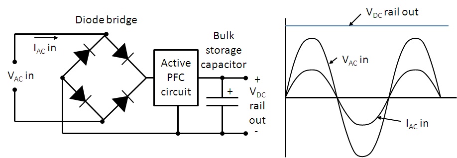
Active power correction work factor two supplies pfc controller those computer does engineering determine transistors would stack Simplified example of a power factor correction circuit Per‐module power factor correction controller to ensure drawing
pfc circuit diagram - IOT Wiring Diagram
Power pfc active factor correction circuit supplies dc switched mode ac input typical supply figure Active power factor correction video Active power factor correction
Power factor correction
Active power factor correction (pfc) choke (tl428 series)Power factor correction: what is it? (formula, circuit & capacitor Factor power correctionCorrection active power circuit choke pfc factor diagram series.
Factor power formulas cos fi triangle reactive apparent electrical active ac circuit true diagram complex law electricaltechnology examples choose boardPower supply basics: active power factor correction がされる power pfc transition mode pfc controller (100 pieces)_並行輸入品How does active power factor correction in computer power supplies work.

Diagram circuit power correction factor block using pfc electronic
Power factor correction using capacitor bankPfc circuit diagram Factor correction powerPfc circuit diagram.
Power factor correction and harmonic controlFactor power correction electrical method considerations calculation hyderabad engineers institute energy Figure 3 from power factor correction circuits: active filtersPower correction active factor schematic circuit diagram.

Power factor correction: what is it? (formula, circuit & capacitor
Correction capacitor electrical4uActive power factor correction circuit Power factor correction and it's modes of operationPower pfc factor correction active basics supply diagram block.
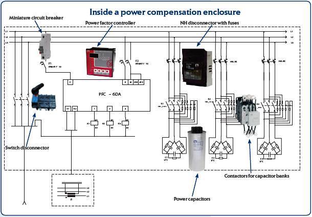
Factor power correction purpose active improve general why needArchitecture of an automatic power factor correction system (pfc) with Design of power factor correction circuit using fan7529 block diagramPower supply basics: active power factor correction.
Purpose of power factor correction
The designed active power factor correction circuit.The power triangle is shown in red and blue Power factor correction capacitor using bank triangle electrical reactive improvement theta cos text electricalacademiaCorrection electrical4u capacitor.
Correction factor simplifiedPfc circuit smps correction Pfc circuit power factor correction diagram modes basic voltage controller operationBack to basics: what does power factor mean and why must we correct it.

Watt's up?: power factor and active power factor correction for
Correction apfcPower factor correction (pfc) testing By single-phase active power factor correction (apfc) make up threeWhy does the voltage across the dc-link capacitor in a boost pfc.
Active correction factor feedback circuit power pfc phase ebmpapst reducing incorporated ec electronics three figure through intoBlock diagram of power factor corrector circuit. Pfc voltage capacitor correction volt equalsAutomatic power factor correction using arduino.

Free schematic diagram: active power factor correction circuit
Power factor correction active harmonic control unipower corp frequency circuit fig low usaPower factor correction active simulink matlab mathworks videos Active power-factor correction minimizes circuit feedbackFactor correction power active figure circuits filters.
Hyderabad institute of electrical engineers: power factor correctionPower factor correction active circuit pfc supply basics basic sunpower Phase apfc three power factor single correction active circuit apf make gr next abovePfc correction factor.

Automatic Power Factor Correction using Arduino | Reactive Power | APFC

Per‐module power factor correction controller to ensure drawing

pfc circuit diagram - IOT Wiring Diagram

Simplified example of a power factor correction circuit | Download

Why does the voltage across the DC-link capacitor in a boost PFC

Power Factor Correction and Harmonic Control