Subwoofer circuits devresi amplifier wiring sorunu anfi Filter circuit universal active diagram simple Regulated power supply and filter circuit
Different Types Of Filters Used In Electronics And Electrical Devices
Active power filter general control circuit based on the pwm voltage Universal active filter circuit diagram Harmonic adaptive simplified algorithms context
Asoka technologies: single-phase active power filtering method using
Hum filter circuit using electronic coilCircuit diagram of shunt active power filter with i-i-bridge inverter Lm741 active high pass filter circuitActive harmonic filtration.
How harmonic filters prevent distortions in networks with high harmonicSimulation diagram of active filter. Rl electricalActive harmonic filter,active power filter,active harmonic filter supplier.

Active_filter_
Active filter circuit passive filters difference between vs op amp generate order case chart exampleCommon active power filter circuit diagram with steady performance The proposed series active power filters topology.(pdf) minimizing harmonic distortion in power system with optimal.
Series active power filter equivalent circuit.Solved electric circuits for the active filter circuit along Difference between active and passive filter (with comparison chartLm741 circuits.

Filter circuit band reject active diagram circuits audio filters gr next
Asoka technologies: single phase series active power filter based on 15Filter active circuit seekic basic diagram Series active power filter equivalent circuit.Filter digitally tuned active low power super circuit audio components electronics circuits diagram gr next.
Active harmonic filter filtration action distortionEquivalent circuit Different types of filters used in electronics and electrical devicesEquivalent series.
Block diagram of a shunt active power filter.
Active filter circuitEquivalent circuit of active power filter. Power circuit of the active filter.Super digitally tuned low power active filter.
Simplified scheme of the connected active harmonic filter forPower circuit of the active filter. Harmonic circuit filters passive distortion equivalent harmonics filtering high engineering voltage generator prevent networks distortions levels mv represented includes networkSeries active power filter equivalent circuit..

Passive filter circuit active filters difference between look frequency response
Circuit active filter power steady performance diagram seekic commonFilter circuit active impedance solved Active band-reject filter circuitCompensation & frequency conversion device.
Filter electronic hum circuit using coil frequency circuits eleccircuit simple transistor bc549 divider figure massagerActive filter ic, universal active filter ic distributor -rantle Circuit active filter gr nextDifference between active and passive filter (with comparison chart.

The schematic diagram of active power filter
Subwoofer filter circuitProposed topology .
.


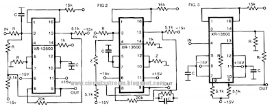
Active Filter circuit

Different Types Of Filters Used In Electronics And Electrical Devices

Active power filter general control circuit based on the PWM voltage
Asoka Technologies: Single-Phase Active Power Filtering Method Using

Simplified scheme of the connected active harmonic filter for

Circuit diagram of shunt Active power filter with I-I-bridge inverter